Rear Suspension
SAFETY FIRST: Protective gloves and eyewear are recommended at this point.
Removal
Remove the rear wheel. See the Rear Wheel topic for more information.
Remove the rear brake caliper. See the Rear Brake Caliper topic.
Remove the side covers. See the Side Covers topic for more information.
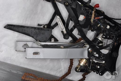
With the motorcycle secured, move the swingarm up and down to check for free play in the rear suspension. If the swingarm has excessive play this could indicate the need for new bearings.
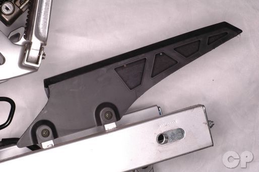


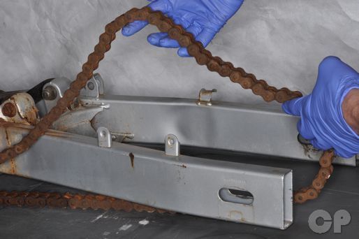
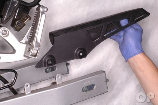
Loosen the two drive chain cover screws with a #3 Phillips screwdriver. Remove the screws, washers, and cover from the swingarm.


Remove the cotter pin from the torque link nut.


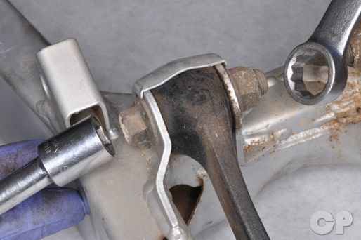
Hold the torque link bolt with a 14 mm wrench and loosen the nut with a 14 mm socket.


Remove the torque link, nut, and bolt from the swingarm.


Free the rear brake hose from the stay on the swingarm.


Hold the upper shock absorber mounting bolt with a 14 mm wrench and loosen the nut with a 14 mm socket.


Remove the upper shock absorber mounting nut and bolt.


Hold the shock arm-to-frame mounting nut with a 19 mm socket and loosen the bolt with a 17 mm socket.


Remove the shock arm-to-frame mounting nut and bolt.
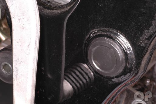


Remove the swingarm pivot caps from the frame.


Hold the swingarm pivot bolt with a 17 mm socket and loosen the nut with a 19 mm socket.
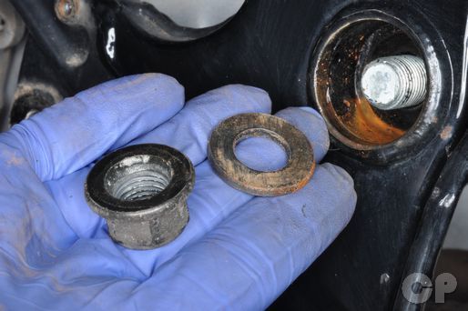
Remove the nut and washer from the swingarm pivot bolt.
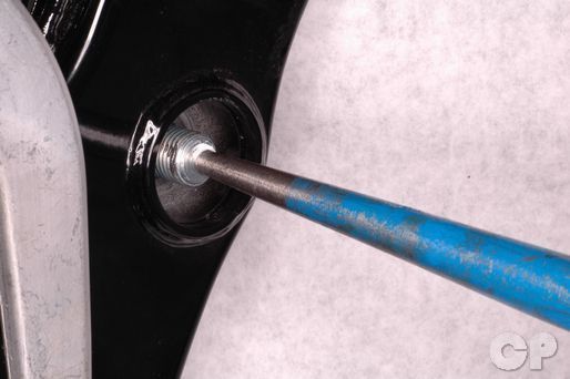


Support the swingarm and tap out the pivot bolt with a flat faced punch and a hammer. Remove the swingarm pivot bolt.
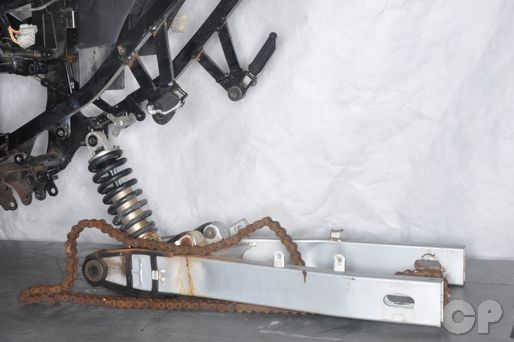
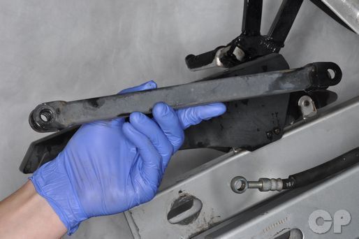
Free the swingarm and rear suspension assembly from the frame.
Remove the chain from the swingarm.
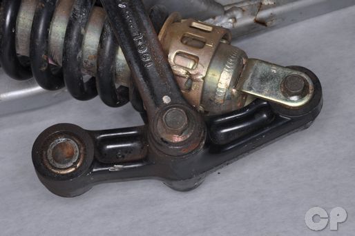


Hold the shock arm-to-connecting link bolt with a 14 mm socket and loosen the nut with a 17 mm socket.


Remove the nut, bolt, and connecting links.


Hold the lower shock absorber mounting bolt with a 12 mm wrench and loosen the nut with a 14 mm socket.


Remove the lower shock absorber mounting bolt and nut. Remove the shock absorber from the linkage.
Hold the connecting link bolt with 17 mm socket and loosen the nut with a 19 mm socket.


Remove the nut, bolt, and the connecting link. Repeat the procedure to remove the other connecting link.
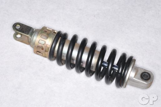
Inspect the rear shock absorber for damage, oil leaks and wear. The shock absorber is not serviceable so it must be replaced if damaged.
To disassemble the rear suspension components see the Rear Suspension Disassembly topic.
Installation
Install the connecting links to the swingarm. The connecting links should sit below the swingarm pivot. Insert the bolts from the outside and thread on the nuts. Hold the connecting link bolts with 17 mm socket and torque the nuts to specification with a 19 mm socket.
(Connecting Link Nut Torque: 84 - 120 N-m or 60.5 - 87.0 lb-ft)
Insert the lower shock absorber mounting bolt from the left side and thread on the nut.
Hold the lower shock absorber mounting bolt with a 14 mm wrench and torque the nut to specification with a 14 mm socket.
(Lower Shock Absorber Mounting Nut Torque: 48 - 72 N-m or 34.5 - 52.0 lb-ft)
Fit the connecting links to the shock arm. Insert the bolt from the left side and thread on the nut.
Hold the shock arm-to-connecting link bolt with a 14 mm socket and torque the nut to specification with a 17 mm socket.
(Connecting Link Nut Torque: 84 - 120 N-m or 60.5 - 87.0 lb-ft)
Fit the chain over the swingarm.


Support the swingarm so that its pivot lines up with the frame. Insert the swingarm pivot bolt from the left side of the frame.
Place the washer on the pivot bolt and thread on the nut.
Hold the swingarm pivot bolt with a 17 mm socket and torque the nut to specification with a 19 mm socket.
(Swingarm Pivot Nut Torque: 65 N-m or 47 lb-ft)


Install the swingarm pivot caps into the frame.
Line up the upper shock absorber mount with the frame. Insert the mounting bolt from the left side and thread on the nut.
Hold the upper shock absorber mounting bolt with a 14 mm wrench and torque the nut to specification with a 14 mm socket.
(Upper Shock Absorber Mounting Nut Torque: 48 - 72 N-m or 34.5 - 52.0 lb-ft)
Insert the frame side shock arm bolt from the left side and thread on the nut.
Hold the shock arm-to-frame mounting bolt with a 17 mm socket and torque the nut to specification with a 19 mm socket.
(Shock Arm Nut Torque: 132 - 192 N-m or 95.5 - 139.0 lb-ft)
Route the rear brake hose through the stay on the swingarm.


Install the torque link to the swingarm. Insert the bolt from the left side and thread on the nut.
Hold the torque link bolt with a 14 mm wrench and torque the nut to specification with a 14 mm socket.
(Torque Link Nut Torque: 20 - 30 N-m or 14.5 - 21.5 lb-ft)
Install the torque link cotter pin and bend it as shown.

Fit the drive chain cover to the swingarm. Install the two cover screws and washers. Tighten the screws securely with a #3 Phillips screwdriver.
Install the brake line to the rear brake caliper. See the Rear Brake Caliper topic for more information.
Install the rear wheel. See the Rear Wheel topic for more information.
Fill and bleed the brake fluid for the rear brake. See the Brake Fluid topic for more information.
Copyright - Cyclepedia Press LLC

Note: If you are viewing this document offline be sure to visit the latest version online at http://www.cyclepedia.com before attempting any repairs. Updates are made without notice.